Introduction to LC Uniboot Fiber Patch Cables
In the past years, to meet the growing bandwidth needs, data center technologies and cabling structures have changed a lot. High density apparently becomes the trend. Data center has to install more and more fiber optic jumper cables in a given space, which makes cable management a more and more difficult problem. New products and technologies are applied to achieve high density in data centers. To find an easy-to-manage and space-saving method for high density cabling becomes an urgent issue for data center managers. In this post, a favorable high density fiber cabling solution—LC uniboot fiber patch cable, which is born to solve problems during high density cabling, will be introduced.
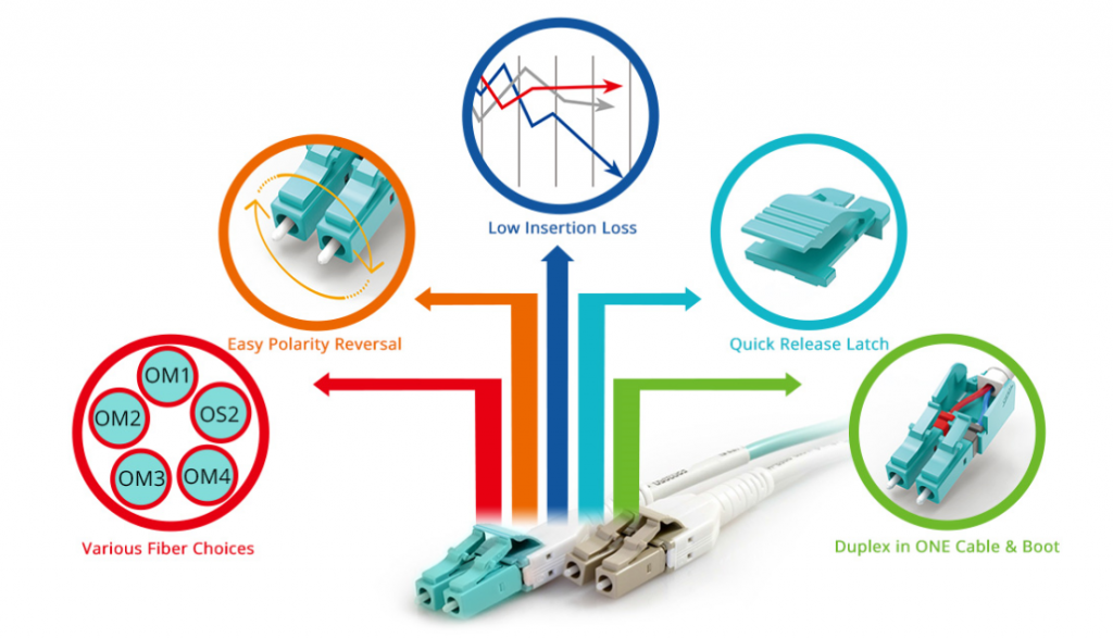
LC Uniboot Fiber Patch Cable vs Standard LC Fiber Patch Cable
LC fiber optic connector can offer higher density and performance in many different environments compared to other types of fiber optic connectors, which makes it a more popular choice for many applications. That is why uniboot fiber patch cables terminated with specially designed LC fiber optic connectors have been invented. With its unique structure, LC uniboot fiber patch cable has more advantages over traditional LC to LC cable in high density cabling environments. Differences between LC uniboot fiber patch cables and standard LC fiber patch cables are noticeable. The following picture shows an LC uniboot fiber patch cable (left) and a standard LC fiber patch cable (right) separately.
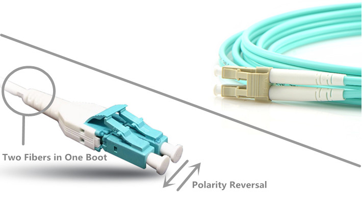
Less Cable Count to Cut Space Requirements
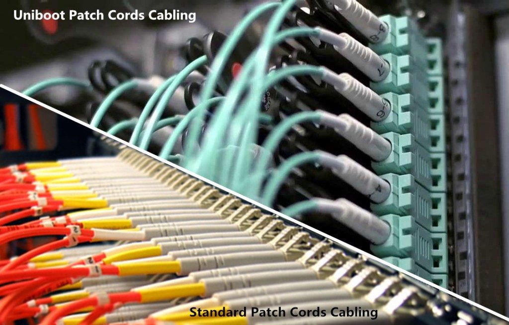
A traditional LC duplex fiber patch cable usually uses a two-cable design with two fibers separately enclosed in two different cables, and it is terminated on each end with a standard duplex LC fiber optic connector. LC uniboot fiber patch cable uses only one cable even it has two fibers. It has a single boot at the back of the duplex LC fiber optic connector. Two fibers for duplex transmission are firmly enclosed in a single cable, which can cut down the cable count up to 50% compared with traditional LC duplex fiber patch cords. Space requirements of data center cabling can be reduced significantly by LC uniboot fiber patch cables.
Easier Polarity Reversal to Increase Efficiency
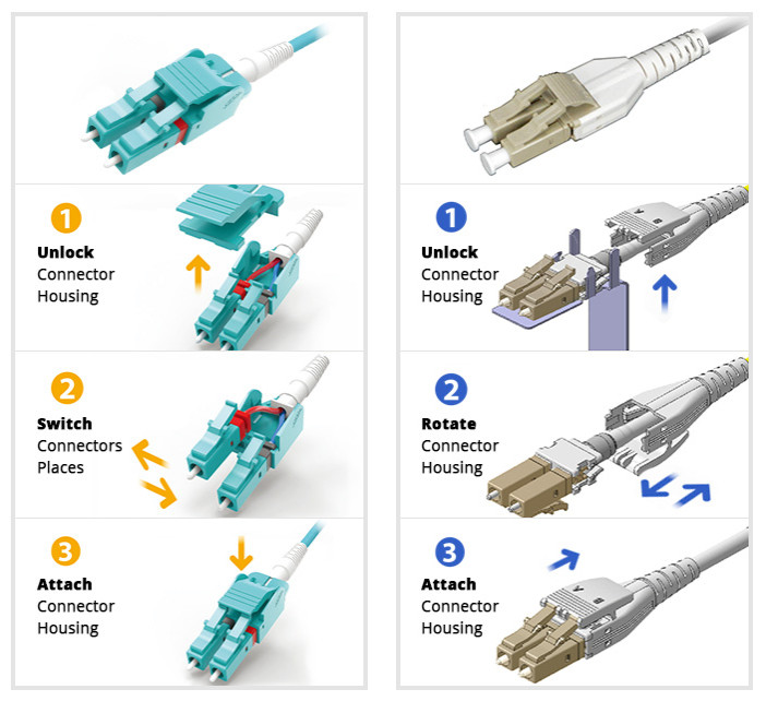
For LC duplex fiber patch cables, polarity change can be really inconvenient, especially in high density cabling environments like data centers. Additional tools and fiber cable re-termination are usually required to change polarity of traditional LC duplex fiber patch cables, which wastes both time and money. And sometimes, improper handling could result in various faults. But the polarity reversal for LC uniboot fiber patch cables is much easier, which can be easily changed by several simple steps without additional tools. Currently, there are several different versions of LC uniboot fiber patch cables, and the polarity reversals of them might differ from each other. Two commonly used versions of LC uniboot fiber patch cables polarity reversal steps are shown in the following picture.
Special Feature to Achieve More Possibilities
With LC uniboot fiber patch cables, fiber optic network design can be more flexible without worrying about spaces and polarity problems. Other than space-saving and easy polarity reversal, LC uniboot fiber patch cable can also achieve more possibilities with its great features. Fiber optic cabling provides faster speeds with reliable quality, which saves a lot of time and money. And, the design and improvement of uniboot fiber patch cables have never stopped. LC uniboot fiber patch cable with push-plug tab has already been available in the market. This little change can make easier finger access and quicker latch release available, and it can also help to connect or disconnect a single fiber patch cable without affecting other surrounding links.
Conclusion
LC uniboot fiber patch cable can help solve problems in high density cable management with high efficiency. It is a more favorable solution compared to standard LC fiber patch cable. LC uniboot fiber patch cable can cut down fiber cabling spaces up to 50% and provide much easier polarity reversal solution. Different kinds of LC uniboot fiber patch cables are available for your applications, such as different cable lengths, different fibers and different cable jackets. You can choose the right one for your needs.
Pre-terminated Fiber Cabling for 40G/100G Data Center Applications
The deployment and termination of fiber optic cabling in data center usually cost a lot of time and labor. However, with the increasingly need for high density cabling in 40G/100G data centers, fiber cabling and termination become even more difficult and time-consuming if traditional field termination methods are still applied. And fiber optic networks are becoming more and more complex, which makes data center cabling becomes more difficult. Risks of faults caused by manual fiber termination will increase. To solve this problem and meet high density requirements of data centers, pre-termianted fiber cabling assemblies are introduced.
Advantages of Pre-Terminated Fiber Cabling
Pre-terminated fiber cabling is relatively a much easier way to install fiber optic cable. The connectors you specify are pre-terminated for you, and the fiber cable you specify is cut to the proper length that you need, such as LC to LC fiber patch cable, SC to LC cable, SC to ST fiber cable, or single mode patch cable, multimode patch cord. Deploying a data center by using field termination methods might need a few days or more. Engineers have to terminate a lot of fiber optic links and connect them to the right ports. To make sure there are no wrong links or bad fiber optic splicing joints, a lot of checking should be done.
However, pre-terminated fiber cable assemblies, using the plug-and-play designed modules and cables, can largely improve the working efficiency, increase cabling density and decrease the total data center installation cost. For example, multi-mode fiber networks for 40G/100G applications use parallel transmission with 8 or 20 fibers per link utilizing 12-fiber MTP/MPO connectors, making it harder to terminate than a single fiber connector. Instead, a pre-terminated MPO cable would be much easier. In addition, the factory terminated fiber cable assemblies eliminate the need of fiber optic splicing and provide higher performance compared with field terminated fiber optic cables.
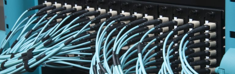
Pre-Terminated Fiber Cabling for 40G/100G Applications
Commonly used pre-terminated fiber cabling assemblies for 40G/100G high density cabling applications are MTP/MPO fiber cable assemblies, including MTP/MPO trunk cable, MTP/MPO harness cable and MTP/MPO cassette. Making good use of these components can largely increase cabling density and working efficiency in data centers.
MTP/MPO Trunk Cable
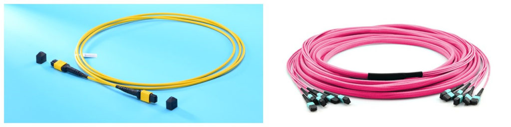
MTP/MPO trunk cable is a length of multi-fiber optical cable, which is usually used for backbone transmission in data center. 12-fiber MTP/MPO trunk cable and 24-fiber MTP/MPO trunk cable are commonly used for 40G and 100G applications separately. Generally, there are two versions of MTP/MPO trunk cable, single-strand MTP/MPO trunk cable and multi-strand MTP/MPO trunk cable. A multi-strand MTP/MPO trunk cable combines several single-stand MTP/MPO trunk cables together. For example, a 72-fiber MTP/MPO trunk cable has 6 strands of 12-fiber cables combining together and each strand is terminated with a 12-fiber MTP/MPO connector.
MTP/MPO Harness Cable
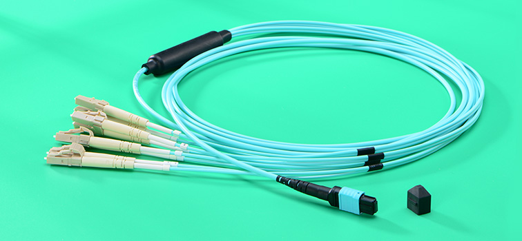
MTP/MPO harness cable is a fanout version of MTP/MPO optical cable. An MTP/MPO fiber optic connector is terminated on one end of the cable, and the fanout end is terminated with several other types of fiber optic connectors, which usually are LC fiber optic connectors. MTP/MPO harness cable is generally used for 40G to 10G transmission or 100G to 10G transmission. MTP/MPO harness cable also has various versions. The most commonly used types are 12-fiber MTP/MPO to 6 duplex LC harness cable for 40G duplex transmission and 24-fiber MTP/MPO to 12 duplex LC harness cable for 100G duplex transmission.
MTP/MPO Cassette
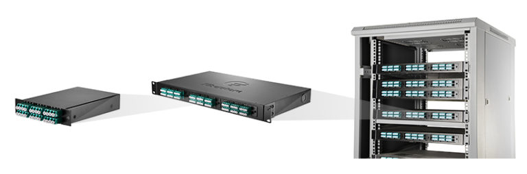
MTP/MPO cassette is a specially designed box which contains one or more small version of MTP harness cables inside it. Generally there is one MTP interface on the back rear of an MTP/MPO cassette and several LC interfaces on its front rear. It can be easily installed on the rack for easier cabling as shown in the following picture. In this way, the fiber optic connections are protected in this box and more fiber optic connections can be added to the data center without worrying about space limitation. The most commonly used are MTP/MPO LGX cassettes. However, driven by increasing need for high density, the size of MTP/MPO cassette gradually decreases. HD MTP/MPO cassette is also available in the market for higher cabling density.
Conclusion
Pre-terminated fiber cable assemblies help accelerate data center deployment, reduce costss and errors, and provide great flexibility and scalability. MTP/MPO cabling system as one of the most popular pre-terminated fiber cabling solutions can perfectly fit the 40G and 100G applications. The above mentioned products are just a really small part of the pre-terminated fiber cable assemblies.
Connectivity Options for 10GbE Infrastructure
10 Gigabit Ethernet (10GbE) now is a commonplace for current network backbones and data centers to support high-bandwidth applications. And with the continuous advancement and improvement in 10GbE technology, it has extended its applications to midmarket networks for the purpose of ensuring faster data transmission and better network performance. How to achieve an efficient and smooth 10GbE network? In this post, several connectivity options for 10GbE infrastructure will be introduced.
Necessities to Deploy 10 Gigabit Ethernet
Nowadays, 10GbE has been an desirable and affordable choice with high performance. And there exists a distinct need for 10GbE networks. The ever-increasing applications require considerable bandwidth to support the transfer and streaming of large data, video and audio files. Besides, rapid and dramatical development of network technologies drive companies to upgrade their current infrastructure and improve its ability to keep pace with the developent. What's more, re-cabling a network can be money-consuming, thus organizations should take precautions to ensure that their cabling systems can perform well in the long run.
Why choose to deploy 10 Gigabit Ethernet? It has several advantages. First, 10 GbE provides the very best assurance for being able to support forthcoming technologies and delivers utmost investment protection. Second, 10 GbE is an ideal technology to move large amounts of data quickly. The bandwidth it provides in conjunction with server consolidation is highly advantageous for web caching, real-time application response, and parallel processing and storage. Moreover, 10GbE campus backbone establishment is a one-time expense that can provide significant cost savings when compared to monthly communications link bills. To implement 10GbE, here are several connectivity options for you.
Option of Fiber Cabling
Fiber cabling is typically used for remote campus connectivity, crowded wiring closets, long-distance communications and environments that need protection from interference, such as manufacturing areas. Fiber cabling is very reliable and less susceptible to attenuation, which makes it an optimum for sending data beyond 100 meters. However, fiber cabling is more costly than copper.
Option of Copper Cabling
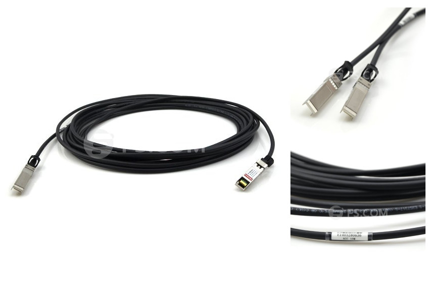
Copper cabling is popular for transmitting data between devices due to its low cost, easy installation and flexibility. Copper is best when utilized in short lengths, typically 100 meters or less. When employed over long distances, electromagnetic signal characteristics hinder performance. In addition, bundling copper cabling can cause interference, making it difficult to employ as a comprehensive backbone. Therefore, copper cabling has become the principal data carrying technique for communication among PCs and LANs, but long-distance transmission. 10G SFP+ direct attach copper cable, such as HP J9281B compatible SFP+ direct attach copper cable, as shown below, is a popular copper solution for 10 Gigabit Ethernet, which has become the main choice for servers and storage devices in a rack for its low latency, small connector and reasonable cost.
Option of Transceiver Modules
Other than the cabling choices, service providers should also pay much attention to the devices that connect their cabling to their networks. There are various transceiver modules available to match each gigabit standard. 10 GbE has four defined transceiver types.
SFP+: SFP+ transceiver, an extension of the SFP optical transceiver, is designed to increase the capacity of the existing SFP module. It has the same mechanical characteristics as the the SFP transceiver, just capable of supporting the higher speed. For many customers, the possibility of achieving 10G speeds and a mechanical form factor that allows 1G or 10G to reside in the same footprint, might prove attractive. It has now become the predominant 10G Ethernet connector type, and branded by many famous companies, like HP, Cisco, Finisar, etc.
XFP: XFP transceiver is the closest in size to the SFP pluggable transceiver now used for gigabit technology. It allows switch vendors to increase port density in a smaller area for cost savings. XFP transceiver cannot support the current 802.3ak copper or the 10GBASE-LX4 standards.
X2: X2 transceiver is about 2/3 the size of XENPAK module. With the same "hot pluggable" specifications and supporting all the 10GbE standards (including copper), the X2 form factor allows for more port density on switches. X2 provides customers with a strong sense of assurance that this technology is the best choice for today and will have strong vendor support.
XENPAK: XENPAK transceiver is the first 10GbE pluggable transceiver on the market to support the 802.3ae standard transmission optics. They are large, bulky and used mainly in LAN switches. These transceivers are "hot pluggable" and support the new 802.3ak copper standard with vendors now producing transceivers to connect CX4 cables.
Conclusion
10 Gigabit Ethernet is commonly used to upgrade networks and support bandwidth-intensive applications. Companies and organizations should have a solid and comprehensive understanding of 10GbE technology before deploying it, which would help to develop a sound migration and cabling method and surely get benefits from 10 Gigabit Ethernet in the long run.
Cabling Solutions for 40G Short Reach QSFP+ Transceivers
40G parallel optical transceivers use four 10G channels to transmit and four 10G channels to receive signals over a 12-fiber assembly. The middle four fibers remain unused or dark. Each fiber either transmits (Tx) or receives (Rx) 10G traffic at a single wavelength. 40gb QSFP+ is the dominant transceiver type and popular choice for 40 Gigabit Ethernet applications. Among all those QSFP+ optics, short reach QSFP+ transceivers are commonly used. This article will introduce cabling solutions for 40G short reach QSFP+ transceivers.
40G Short Reach QSFP+ Transceivers
In 2010, 40GBASE-SR4 parallel optics solution for MMF was released by IEEE standard 802.3ba as one of several 40G based solutions. Later, another solution 40GBASE-CSR4 was released. 40GBASE-CSR4 is similar to 40GBASE-SR4 but it extends the distance capabilities. These two multi-mode transceivers can also support 4x10G modes. This part will tell details about these two short reach 40G parallel optical QSFP+ transceivers.
40GBASE-SR4 QSFP+: 40GBASE-SR4 QSFP+ transceiver enables high-bandwidth 40G optical links over 12-fiber parallel fiber terminated with MPO/MTP multi-fiber female connectors. It can support link lengths of 100 meters and 150 meters over OM3 and OM4 multimode fibers respectively. 40GBASE-SR4 QSFP+ transceiver can also be used to connect with four 10GBASE-SR optical interfaces using an 8-fiber MTP to 4 duplex LC cable.
40GBASE-CSR4 QSFP+: 40GBASE-CSR4 QSFP+ transceiver can be used for native 40G optical links over 12-fiber parallel cables with MPO/MTP connectors or in a 4x10G mode with parallel to duplex fiber breakout cables for connectivity to four 10GBASE-SR interfaces. It can extend the reach of 40GBASE-SR4 interface to 300 and 400 meters over OM3 and OM4 multimode parallel fibers respectively.
Cabling Solutions for Short Reach QSFP+ Transceivers
To connect a parallel optics 40GbE short reach transceiver to another short reach 40GbE transceiver, a Type-B female MTP/MPO to female MTP/MPO cable is required. The following picture shows two 40GBASE-SR4 QSFP+ transceivers being connected with a female MTP cable. The fiber position (from 1 to 12) is reverse on the ends of the assembly. This reverse fiber positing allows signals to flow from transmission on one end of the link to reception on the other end. This type of direct connectivity is only suggested for short distances within a given row of racks/cabinets. It has less robustness (less tensile strength, less crush and impact resistance, etc.) than a distribution-style cable, which would be used for structured cabling trunks.

In addition to this, there are several other cabling solutions for parallel optics 40G short reach connectivity. Solution one, in the interconnect structured cabling system, MTP trunk cables will be deployed by placing them in cable trays without the fear of them being crushed.

Solution two, with 2×12 to 3×8 or 1×24 to 3×8 harness cable assembly, 100% fiber utilization will save the cost of fiber utilization in the structured cabling. And it also saves the cost of labor and materials. Make sure that each MTP connector is plugged into a port.

Solution three, this approach uses 40G channel interconnect structured with conversion devices: 2×3 or 1×3 modules. It can utilize 100% of the installed fiber as harnesses. It is easily accomplished by using Type-B non-pinned MTP to non-pinned MTP jumpers.

Conclusion
With the increasing demand for high-bandwidth applications such as cloud computing, server virtualization and fabric consolidation within data centers, the trend for faster data transfer rates like 40G and 100G is relentless. There are various types of 40GbE transceivers, MPO/MTP cables like MPO/MTP trunk cable and MPO/MTP harness cable, MPO/MTP cassette and other assemblies for your 40G network connectivity. You just need to make sure that you choose the right one.
Introduction to Digital Diagnostic Monitoring
Cisco GLC-SX-MMD transceiver is a 1000BASE-SX SFP optical transceiver. This hot-swappable input/output device plugs into a Gigabit Ethernet port or slot and allows the port to be linked with the network via multimode optical fiber. Cisco GLC-SX-MMD transceiver is a replacement of Cisco GLC-SX-MM transceiver. The module numbers of these two SFP transceivers differ only in one letter "D". This "D" mainly represents a function named DDM, which is inherited by many fiber optic transceivers offered today. What is this DDM function? Why this DDM function can offer GLC-SX-MMD transceiver advantages over GLC-SX-MM transceiver? This article will help you understand DDM.
What Is DDM?
DDM is short for digital diagnostic monitoring according to the industry standard MSA (Multi-Source Agreement) SFF-8472 and is also known as DOM (digital optical monitoring). When selecting fiber optic transceivers today, you can choose transceiver modules with or without DDM/DOM function. Most of fiber optic transceivers now are with the DDM function. This technology allows the user to monitor real-time parameters of the fiber optic transceivers, like optical input/output power, temperature, laser bias current, and transceiver supply voltage, and so on.
What Can DDM Do?
DDM can provide component monitoring on transceiver applications in details. The SFF-8472 added DDM interface and outlined that DDM interface is an extension of the serial ID interface defined in GBIC specification, as well as the SFP MSA. DDM interface includes a system of alarm and warning flags which alert the host system when particular operating parameters are outside of a factory set normal operating. Thus, DDM interface can also enable the end user with the capabilities of fault isolation and failure prediction. This part will explain what can be done with DDM.
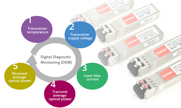
Component Monitoring: DDM enables the end user to monitor key parameters in the performance of fiber optic transceivers. The real-time diagnostic parameters can be monitored to alert the system when the transceiver's specified operating limits are exceeded and compliance cannot be ensured. These key parameters includes:
- Transceiver temperature
- Transceiver supply voltage
- Laser bias current
- Transmit average optical power
- Received optical modulation amplitude (OMA) or Average Optical Power
Fault Isolation: DDM function can be used to isolate the particular location of fault in fiber optic network systems. Combining the DDM interface status flags, transceiver hard pins and diagnostic parametric monitor data the specific location and cause of a link failure can be pinpointed.
Failure Prediction: DDM can also be used to help predict failure on fiber optic links, which is based on the transceiver parametric performance. Although, this application is not yet fully mature, but there is still room for improvement. There are two basic types of failure conditions that can be seen on fiber optic transceivers. One is device faults, which means non-operation or malfunction of a device and is typically applied to transmitter performance, due to nature of semiconductor lasers. The other is high error rate conditions, which means operating conditions are such that a fiber optic transceiver is operating at its signal-to-noise limit, and is applied more to fiber optic receiver performance.
Conclusion
Providing parameter monitoring, fault isolation, and failure prediction, fiber optic transceivers with DDM help to ensure that the business can be proactive in preventative maintenance of the network and ensure business continuity. So it would be easy to explain why modern transceivers are with DDM and why GLC-SX-MMD SFP optical transceiver can replace GLC-SX-MM SFP optical transceiver. It is an irresistible trend of industry and technology development. Although fiber optic transceivers with DDM function are much more popular than those without DDM, some users still choose the older optical transceivers in consideration of the upgrading costs.
Usage of Direct Attach Cables for Data Center Interconnection
Direct attach cable assemblies are becoming more and more popular among data center operators, for they use the same port as optical transceivers but with significant cost savings and power savings in short reach applications. These assemblies are mainly used to support high transfer rates between servers, switches and storage devices in data centers. In this post, we will talk about the usage of direct attach cable assemblies for data center interconnection.
Types of Direct Attach Cables
Direct attach cable assemblies are terminated with transceiver-style plugs, such as SFP+ (enhanced small form-factor pluggable), SFP28, QSFP+ (quad small form-factor pluggable), QSFP28, and CXP, etc. Using the same port as transceiver optics, direct attach cables can support Ethernet, Infiniband and Fibre Channel but with independent protocols. In general, direct attach cable assemblies are divided into three families—direct attach passive copper cable, direct attach active copper cable and active optical cable (AOC).
Passive Direct Attach Copper Cable
Passive direct attach copper cables are without active circuitry component. They can achieve interconnections up to 7m at 10 Gbps or 40 Gbps with low power. Direct attach passive copper cable assemblies, like HP J9281B SFP+ passive direct attach copper cable, offer high-speed connectivity between equipment. They are compatible with hubs, switches, routers, servers, and network interface cards (NICs) from leading electronics manufacturers like Cisco, Juniper, etc.

Active Direct Attach Copper Cable
Active copper cables are designed in the same cable type as the passive one, but they contain low power circuitry in the connector to boost the signal and are driven from the port without additional power requirements. The active version provides a low cost alternative to optical transceivers, and are generally used for end of row or middle of row data center architectures for interconnect distances of up to 15 meters.

Active Optical Cable
Active optical cable (AOC) incorporates active electrical and optical components. It can achieve longer distance than the copper assemblies. In general, active optical cable can reach more than 100m via multimode fiber. Compared to direct attach copper cable, AOC, like Cisco SFP-10G-AOC10M SFP+ AOC, weighs less and can support longer transmission distance. It is immune to electromagnetic energy since the optical fiber is dielectric (not able to conduct electric current). And it is an alternative to optical transceivers and it can eliminate the separable interface between transceiver module and optical cable. However, it costs more than copper cable.

In addition, with the fan-out technology, both direct attach copper cable and active optical cable can be designed as breakout direct attach cable assemblies, like 40G QSFP+ to 4x10G SFP+ AOC, which can better satisfy the demands on network migration.
Direct Attach Cables for Data Center Interconnection
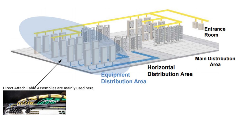
Direct attach cable assemblies are ideal choices for short-reach direct connection applications. Generally, they are used in the EDA (Equipment Distribution Area) where cabinets and racks house end equipment (servers) and where horizontal cabling from the HDA (Horizontal Distribution Area) are terminated at patch panels, as shown in the following picture:
For interconnection in racks and between rows of racks, direct attach cable assemblies are used to connect server to switch, storage to switch or switch to switch. Depending on different interconnect applications and distance requirements, direct attach copper cables, passive or active, active optical cable, or breakout direct attach cable assemblies with various length options can be used.
As 10G network is widely deployed in today's data center, 10G SFP+ DACs are commonly used in interconnect applications below 15m, such as server to switch or storage to switch interconnection in the same rack. And now 25GbE is popular and 25G direct attach cable assemblies, such as SFP28 DACs, are already available in the market. For 40GbE, 40G QSFP+ DACs and AOCs are used. Of course, higher speed and more bandwidth are needed for spine switches. Thus, 100G DACs, like QSFP28 DACs are used in this case.
Conclusion
There are a wide range of direct attach cable assemblies available for you, including both direct attach copper cable assemblies and active optical cables. They can cover data rates of 10G, 25G, 40G, 100G and even 120G. For your 10G networks, you can choose SFP+ direct attach cables; for your 40G networks, QSFP+ direct attach cables. And both copper and optical fiber options are available. You need to know more about them first and then make the right choice.
What Affects the Optical Transmission Distance?
Optical network has now been more and more popular now, for it has several advantages, such as high speed, high bandwidth and high density. And fiber optic cables can support much longer distance than traditional copper cables (like twisted pair cables or coaxial cables). However, in practice, the distance that fiber optic cable can support is affected by many factors. Transmission distances of optical links vary from meters to hundreds of meters and kilometers, but optical signals may become weak over long distances. What affects the transmission distance? This article will talk about several factors that affect optical transmission distance.
Type of Fiber Optic Cable
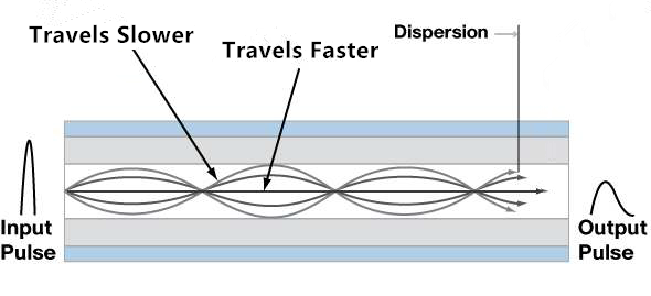
Generally, the maximum transmission distance is limited by the dispersion in fiber optic cables. There are two types of dispersion that can affect the optical transmission distance—chromatic dispersion and modal dispersion. Chromatic dispersion is the spreading of signals over time resulting from different speeds of light rays. Modal dispersion represents the spreading of the signals over time resulting from different propagation modes.
For single-mode fiber optic cable transmission, it is chromatic dispersion that affects the transmission distance. The reason is that the core of a single-mode fiber optic cable is much smaller than that of a multimode optical cable, and only allows one mode of light to propagate. Single-mode optical cable can transmit signals over longer distance than multimode optical cable. Multimode optical cable transmission is largely affected by modal dispersion, because these optical signals cannot arrive simultaneously and there is a delay between the fastest and the slowest modes, which causes the dispersion and limits the performance of multimode fiber optic cables, as shown in the following picture.
Light Source of Fiber Optic Transceiver
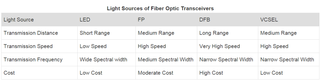
Fiber optic cable is the path for the transmission of optical signals. However, most of the terminals are electronic based, so the conversions between electrical signals and optical signals are very necessary. And this process largely depends on fiber optic transceivers, which are commonly used in most of today's fiber optic networks. LED (light emitting diode) or laser diode inside are the light sources of fiber optic transceivers, which can also affect the transmission distance of a fiber optic link.
LED diode based transceivers can only support short distances and low data rate transmission. They cannot satisfy the increasing demand for higher data rates and longer transmission distances. For higher transmission data rates, laser diodes are used. Several commonly used laser sources in fiber optic transceivers are Fabry Perot (FP) laser, Distributed Feedback (DFB) laser and Vertical-Cavity Surface-Emitting (VCSEL) laser. For example, TRENDnet TEG-MGBSX SFP transceiver is a 1000BASE-SX SFP transceiver module with a VCSEL laser transmitter, which can support a data rate of 1.25Gbps and 550m transmission distance. The following table shows the main characteristics of these light sources.
Splices and Connectors
Splices or connectors are inevitable in many fiber optic systems. Signal losses can be caused when optical signals pass through each splice or connector. The amount of the loss depends on the types, quality and number of connectors and splices. For example, signal loss through an LC LC multimode duplex fiber cable may not be the same with an ST ST multimode duplex fiber cable.
Frequency of Transmission
As mentioned in the above table, different laser sources support different frequencies. The maximum distance an optical system can support is also affected by the frequency at which the signals are transmitted. Generally the higher the frequency is, the longer distance the optical system can support. Thus, choosing the right frequency to transmit optical signals is quite necessary.
Bandwidth
The bandwidth that fiber optic cable supports is another important factor that influences the transmission distance. As the bandwidth increases, the transmission distance usually decreases proportionally. For instance, a fiber that can support 100 MHz bandwidth at a distance of 5 kilometers will only be able to support 250 MHz at 2 kilometers and 500 MHz at 1 kilometer.
Summary
There are many factors that affect the optical transmission distance, such as the type of fiber optic cable, light source of fiber optic transceiver, splices and connectors, frequency of transmission, bandwidth that the network supports. All these factors need to be taken into consideration during the deployment of fiber optic networks to minimize the limitations on the transmission distance.
